

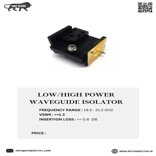
Description
A Waveguide Isolator is a non-reciprocal microwave passive device that allows electromagnetic signal power to pass in one direction with very low insertion loss while absorbing or attenuating reflected signals traveling in the reverse direction.It relies on magnetized ferrite material to exploit non-reciprocal gyromagnetic phenomena (such as Faraday rotation or resonance absorption).Core Purpose & FunctionIn high-power RF and microwave systems, impedance mismatches along a transmission path or at an antenna can reflect microwave energy back toward the transmitter source (such as a klystron, magnetron, or solid-state power amplifier).Without isolation, reflected power can cause:Frequency Pulling: Unstable oscillation and frequency drift in power sources.Component Damage: High voltage standing waves (VSWR) breaking down power amplifier stages.Signal Distortion: Intermodulation and phase interference in high-data-rate links.Inserting a waveguide isolator right after the RF source acts as a one-way check valve, protecting the transmitter regardless of downstream load mismatches.Common Types of Waveguide IsolatorsFaraday Rotation Isolator:Uses a ferrite rod inside a circular waveguide section subjected to an axial magnetic field.Rotates the polarization angle of the forward wave by $45^circ$, allowing it to align with the output waveguide flange.Any reverse-traveling wave is rotated an additional $45^circ$ in the same rotational sense (total $90^circ$ mismatch relative to input plane) and gets absorbed by a internal resistive vane.Resonance Absorption Isolator:Places ferrite slabs at precise locations inside a rectangular waveguide where the RF magnetic field is circularly polarized.A static DC magnetic field tunes the ferrite's electron spin precession frequency to match the RF signal frequency (ferromagnetic resonance).Forward waves pass with minimal interaction, but reverse waves match the precession sense and get heavily absorbed as heat.Field Displacement / Termination Circulator Type:Utilizes a 3-port waveguide circulator with Port 3 internally terminated with a high-power $50 Omega$ load.Signals flow from Port 1 to Port 2. Any reflections returning into Port 2 are routed entirely into the matched load at Port 3 and dissipated.Key Technical ParametersParameterTypical Value RangeDescriptionIsolation$18text{ dB to } 30+text{ dB}$Ratio of reverse power attenuationInsertion Loss$0.2text{ dB to } 0.8text{ dB}$Power loss experienced by the forward signalVSWR$1.10:1 text{ to } 1.25:1$Impedance match quality at input/output portsPower HandlingWatts to Megawatts (Peak)Maximum average/peak RF power before breakdownWaveguide StandardWR-28 to WR-430 (K-band to L-band)Standardized rectangular flange sizesPrimary ApplicationsRadar Systems: Protecting high-power transmitter tubes (magnetrons/TWTs) from antenna reflections during rotation.Satellite Ground Stations: Maintaining clean power amplifier output across high-power uplink feeds (Ku, Ka, X-band).Test & Measurement: Shielding sensitive signal generators and vector network analyzers (VNAs) during device testing.
other Products
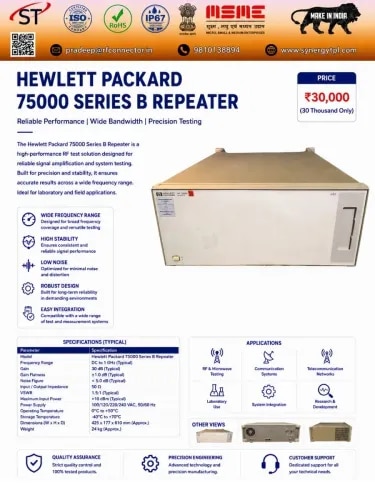 HEWLETT PACKARD Hewlett-Packard (HP) 75000 Series B is a modular VXIbus instrumentation platform designed for automated electr
HEWLETT PACKARD 75000 S...
INR 30000- AGILENT Agilent E4408B ESA-L Spectrum Analyzer is a professional RF and microwave spectrum analyzer covering a frequen
AGILENT E4408B SPECTRUM...
INR 750000 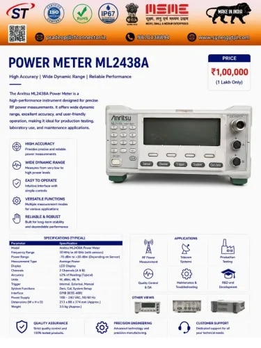 ANRITSU Anritsu ML2438A Power Meter is a high-performance dual-channel RF and microwave power measurement instrument d
ANRITSU ML 2438A POWER ...
INR 100000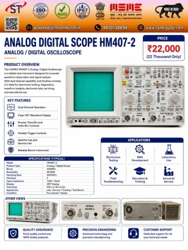 HAMEG HAMEG HM407-2 is a 40 MHz, two-channel analog/digital storage oscilloscope designed for laboratory, service, e
HAMEG HM407 -2 ANALOG /...
INR 22000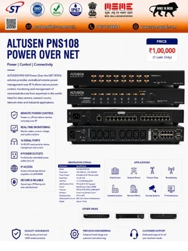 ALTUSEN ALTUSEN PN9108 Power Over the NET™ is an 8-port network-controlled AC power management device designed to prov
ALTUSEN PNS108 POWER OV...
INR 100000