
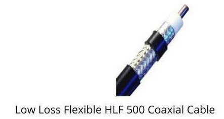
low loss flexible hlf 500 coaxial cable
INR 105
Enquire
Description
1. Core Electrical Properties Frequency Range: DC to 6 GHz (optimized performance up to 12 GHz) Impedance: 50Ω ±0.35Ω Velocity Factor: 85% Attenuation Characteristics: Frequency Max Attenuation 100 MHz 0.06 dB/ft 500 MHz 0.14 dB/ft 1 GHz 0.20 dB/ft 3 GHz 0.35 dB/ft 6 GHz 0.50 dB/ft 2. Mechanical Construction Outer Diameter: 0.525“ (13.3mm) Conductor: Silver-plated copper-clad aluminum (0.148” diameter) Dielectric: Dual-layer foam PE with air gaps (0.385“ OD) Shielding: Triple-shield configuration: Bonded aluminum foil (100% coverage) Tinned copper braid (95% coverage) Silver-plated copper braid (98% coverage) Jacket: Abrasion-resistant polyurethane (0.040” thickness) 3. Power Handling Capacity Frequency Continuous Power Peak Power (1µs pulse) 100 MHz 5 kW 50 kW 1 GHz 2.5 kW 25 kW 3 GHz 1.2 kW 12 kW 6 GHz 600 W 6 kW 4. Environmental Specifications Temperature Range: Standard: -40°C to +85°C Extended: -55°C to +125°C (special order) Bend Radius: Minimum static: 5“ (12.7cm) Minimum dynamic: 10” (25.4cm) Flex Life: 8,000+ cycles at rated bend radius Crush Resistance: 300 lbs/ft (450 kg/m) 5. Special Performance Features Phase Stability: ±1.2° per 100ft @ 3GHz EMI Shielding Effectiveness: >130 dB @ 1GHz VSWR: <1.20:1 up to 6 GHz Capacitance: 28.5 pF/ft 6. Comparative Analysis Parameter HLF-500 LMR-500 RG-214 Ecoflex 15 3 GHz Loss 0.35 0.45 0.80 0.30 Flex Rating ★★★★☆ ★★★☆☆ ★★☆☆☆ ★★★★★ Power @ 1GHz 2.5 kW 1.8 kW 1.2 kW 3.0 kW Cost Factor 1.2x 1.0x 0.6x 1.8x 7. Recommended Applications Mobile cellular base stations Satellite communication terminals Military field deployable systems High-power RF test equipment Broadcast transmitter links 8. Connector Compatibility Standard N-Type: Times Microwave N5M-500 7/16 DIN: Huber+Suhner 09.0158 TNC: Amphenol 31-221-RFX Precision SMA: Southwest Microwave 292-04A-5 (for high-frequency use) 9. Installation Best Practices Support Interval: Every 3 feet for horizontal runs Bending: Use forming tools for radii <8“ Termination: Strip length: 0.75” ±0.02" Shield prep: Unbraid and fold back second braid layer Grounding: Install grounding kits every 30 feet 10. Quality & Compliance Standards: MIL-DTL-17/189 (Rev. F) IEC 61196-4 RoHS 3 compliant Certifications: UL AWM Style 1672 CE Marked REACH SVHC compliant 11. Procurement Options Standard Packaging: 250ft and 500ft continuous lengths 50ft pre-terminated assemblies Special Variants: Pressurizable version (10 psi operating) Direct burial version with flooding compound Phase-matched sets (±0.75° @ 3GHz)
other Products
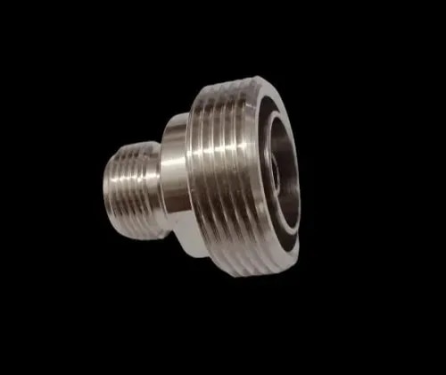 RF CONNECTOR HOUSE The DIN(F) to DIN(F) Adaptor 7.5GHz is a precision 50Ω RF coaxial adapter designed to provide a secure female
DIN(F) TO DIN(F) ADAPTO...
INR 300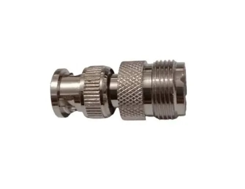 RF CONNECTOR HOUSE The BNC(M) to UHF(F) Adaptor 3GHz is a high-quality 50Ω RF coaxial adapter designed to connect a BNC male inte
BNC(M) TO UHF(F) ADAPTO...
INR 120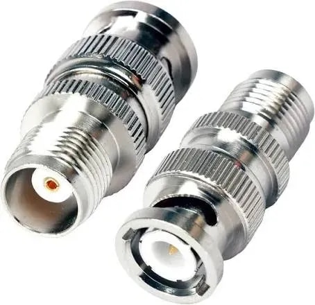 RF CONNECTOR HOUSE The BNC(M) to TNC(F) Adaptor 3GHz is a precision 50Ω RF coaxial adapter designed to connect a BNC male interfa
BNC(M) TO TNC(F) ADAPT...
INR 110 RF CONNECTOR HOUSE The BNC(M) to TNC(F) Adaptor 3GHz is a precision 50Ω RF coaxial adapter designed to connect a BNC male interfa
BNC(M) TO TNC(F) ADAPT...
INR 110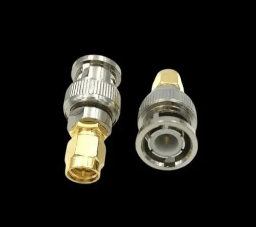 RF CONNECTOR HOUSE The BNC(M) to SMA(M) Adaptor 3GHz is a high-quality 50Ω RF coaxial adapter designed to connect a BNC male inte
BNC(M) TO SMA(M) ADAPTO...
INR 100