Description
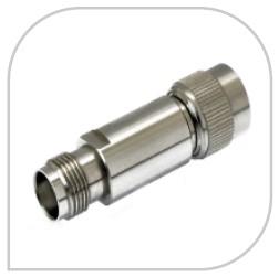
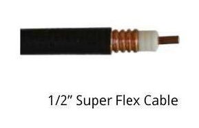
1. Core Specifications Impedance: 50Ω (±0.5Ω) Outer Diameter: 0.5“ (12.7mm) Frequency Range: DC-18 GHz (with proper connectors) Bend Radius: 2.5” (6.4cm) minimum (dynamic), 1.5“ (3.8cm) (one-time install) Power Handling: 1.5 kW peak @ 30 MHz 300W average @ 1 GHz 50W @ 10 GHz Attenuation: Frequency Loss (dB/100ft) 100 MHz 1.8 1 GHz 5.9 6 GHz 15.2 18 GHz 28.7 2. Construction Details Layer Material Key Properties Center Conductor Silver-plated copper-clad steel 0.109” diameter, 85% conductivity Dielectric PTFE foam 0.85 εᵣ, crush-resistant Outer Conductor Dual-layer: 1) Silver-plated copper tape 2) Tinned copper braid (95% coverage) EMI shielding >120 dB Jacket Fluoroelastomer (FEP) -65°C to +200°C operating range 3. Connector Compatibility N-Type: Reliable up to 11 GHz TNC: Vibration-resistant for mobile use SMA: For 18 GHz+ applications 7/16 DIN: High-power variant (up to 1kW @ 1GHz) Recommended Connectors: Amphenol SF1119-ND (N-type, 360° crimp) Times Microwave SFT-500 (SMA, field-installable) 4. Key Advantages vs. Standard RG-214 Feature Superflex 1/2“ RG-214 Bend Radius 2.5” 6“ Flex Cycles >10,000 <1,000 Weight 0.15 lb/ft 0.28 lb/ft Max Freq 18 GHz 6 GHz 5. Installation Guidelines Preparation: Strip cable with 1.5” jacket removal Fold back braid at 45° angle Trim dielectric to expose 0.2“ center conductor Connector Assembly: Use hex crimp tool (Jonard UC-5000 recommended) Torque to 12 in-lbs for SMA, 20 in-lbs for N-type Routing: Avoid sharp edges (use ceramic guides if needed) Support every 12” in vertical runs 6. Environmental Ratings Waterproof: IP68 (with proper connectors) UV Resistance: MIL-DTL-17G compliant Flame Rating: IEEE 1202 FT4 7. Common Applications Military/Aerospace: Radar systems, drone links Telecom: 5G mmWave fronthaul Medical: MRI RF coils Test Equipment: VNA extensions 8. Ordering Options Standard Lengths: 1m to 500m reels Custom Configs: Pre-terminated assemblies Special Variants: SF-500-NUC: Nuclear-hardened SF-500-OF: Oxygen-free copper center 9. Maintenance Annual: VSWR sweep (1-18 GHz) 5-Year: TDR analysis for impedance bumps 10-Year: Jacket integrity testing